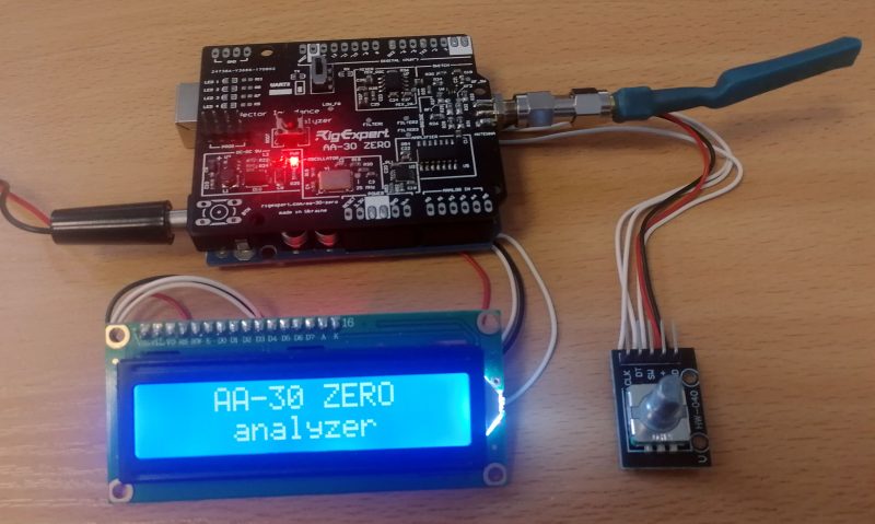
Arduino + AA-30.ZERO = tiny analyzer
Dear friends!
AA-30.ZERO is an excellent tiny antenna analyzer that works in conjunction with PCs and AntScope and AntScope2 software and allows you to measure antennas and feeder lines in the range from 100 kHz to 170 MHz!
Based on the new library for Arduino RigExpertZero, I developed a small test design of a portable analyzer that performs measurements in the frequency range from 1 to 30 MHz without using a PC.
The following components were used in the project:
Arduino UNO
LCD display i2c
Rotary encoder
AA-30.ZERO
You can find out about the library features in this article.
I connected the modules to each other with short wires using soldering. This is a more reliable method than connecting through a bread board.
After you connect all the modules together, upload the sketch to Arduino. In order for the sketch to compile correctly, additional libraries must be installed.
Links to used libraries:
For display operation:https://rigexpert.com/files/libraries/LiquidCrystal_I2C_V112/
For the analyzer to work: https://rigexpert.com/files/libraries/RigExpertZero/
For encoder operation: https://rigexpert.com/files/libraries/GyverEncoder/
https://rigexpert.com/files/libraries/encTest/
Download source code here.
After a successful download, the welcome message “AA-30 ZERO analyzer” will be displayed on the screen for 4 seconds.
If this message is missing, check if the modules are connected correctly.
Important information! For the RigExpertZero library to work correctly, analyzer firmware no lower than version 2.0 is required. You can update the firmware using the FlashTool utility.
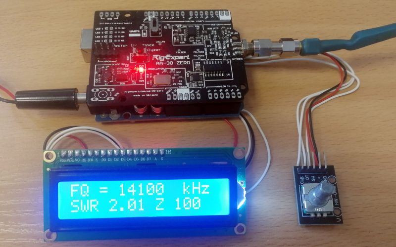
After 4 seconds, the analyzer is ready for operation. You can change the operating frequency by turning the encoder knob. Standard rotation to the right and left changes the frequency value by step 10 kilohertz. Rotating the knob while pressing changes the frequency by step 1 megahertz.
Pressing the encoder knob starts a single measurement.
In this version, the value of the SWR and the value of the impedance module are displayed on the screen.
This project is a test project and is designed to test the library’s functionality. You can modernize the source code, and add different modules (keyboards, graphic displays) and functions.
You will surely succeed!
Do not forget to share with us the result of your work.
You can write all questions and suggestions to the email: [email protected]
Respectfully,
Alex Antonov UR4MCB


