How to make and tune the 50 MHz Yagi Antenna
Creating the 6-element antenna and evaluating it
using the RigExpert AA-55 ZOOM Antenna and cable analyzer
The Sun is approaching its 11-year cycle maximum, and propagation on high-frequency bands, including 6 meters, is improving. An effective multi-element directional antenna is a MUST for serious DX work on the so-called “Magic Band”.
- Choosing the prototype model.
Many different antenna designs by different authors are available, but those by Martin Steyer DK7ZB have proven reliable and effective. Therefore, the following prototype for this homemade antenna was chosen: https://www.qsl.net/dk7zb/6m/650.htm
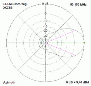
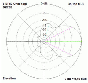
It isThe 6-Element-50-Ohm-Yagi with 6,00m-Boom. H-plane, the Medium Bandwidth, High-Gain-Design with perfect Pattern, and 9,46 dBd (11,61 dBi) gain design.
The author gives the initial dimensions for 12mm diameter elements in Table 1. This is the starting point in building the own antenna.
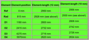
Table 1
- Adapting the homemade design to the chosen model.
The next step would be to use antenna modeling software to verify the chosen model and adjust it to the materials being used in this homemade design.
MMANA-GAL modeling software http://gal-ana.de/basicmm/en/ was used to do this job:
- Create a model based on the original DK7ZB dimensions and calculate it to verify if the radiation pattern and input impedance correspond to the original antenna.
- If telescopic elements are used instead of 12mm ones, it will be necessary to adjust the length of the elements using the “Edit → Taper wire set” option in MMANA. In this particular case, the taper schedule would be from 16mm to 12mm to 8mm.
- Begin the calculation process for the “tapered” design and compare the following parameters: R (Ohm), X (Ohm), SWR, Ga dBi, and F/B dB to the original parameters.
- Press “Plots → Detailed” buttons, and the antenna patterns within the chosen bandwidth will show up.
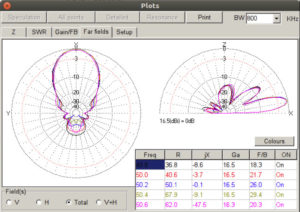
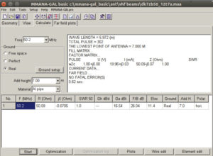
The mechanical design phase can begin if the calculated parameters meet the design objectives.
If the resonant frequency is not close to the calculated value, then the tips of all elements must be adjusted iteratively and equally at both ends. For example, shortening all elements of a 6m Yagi antenna by 1cm or 0.33% can move the SWR curve up by approximately 160 KHz.
It is strongly recommended to carry out parameter recalculations after every iteration.
Table 2. The final calculated dimensions (Spacings from the rear and tapered element lengths).
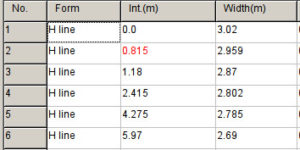
Note: the length of the driven element includes the lengths of coaxial cable ends.
The antenna was built and initially tested using the RigExpert AA-55 ZOOM analyzer at a height of 3 meters above the reinforced concrete roof of the building.
The results were encouraging, with an SWR of 1.13. The antenna was then raised to a height of 8 meters above the roof.
At the height of almost 1.5 wavelengths from the roof, which acts as a “ground plane,” the SWR was 1.02, and all other parameters at the design frequency fully corresponded with both the MMANA-GAL calculations and the DK7ZB prototype characteristics.

