ZERO II: the tiny and powerful analyzer
We created a second version of the beloved tiny AA-30.ZERO analyzer that users enjoy two years ago. The new project’s name, ZERO II, embodies its core values of versatility and simplicity.
It is based on the feedback received from our customers and our experience.
The ZERO II has the following characteristics:
- Frequency range: from 100 kHz to 1 GHz
- Size: 55*35 mm
- User interfaces: HID, UART, I2C, SPI
- USB connector (for firmware updates, power supply, and connection to gadgets via OTG)
- Power consumption: about 120 mA in measurement mode
- Antenna connector: SMA
- Weight: 10 grams
ZERO II has a unique feature of connecting to Android-based gadgets and the AntScope application via OTG connection. This feature allows you to use only a smartphone and an analyzer without developing programs for Arduino, Raspberry Pi, or any other microcomputers.
In this article, we would like to consider an example of a simple project of a portable antenna analyzer using Arduino UNO, a 20*4 I2C LCD, an encoder, and our new RigExpert ZeroII_UART library.
Links to libraries that were used in creating the sketch:
- RigExpertZeroII_UART
- LiquidCrystal_I2C
- Wire.h
- EEPROM.h (standard libraries included in the basic set)
- You can download the latest version of the sketch here.
Important! To work with ZERO II, Arduino, and RigExpertZeroII_UART libraries, a special version of firmware must be flashed onto the analyzer. This version reduces the data exchange speed via UART protocol from 115200 to 38400 baud.
You can download the firmware from this link.
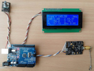
Here is a general photo of the prototype
Of course, for practical use, all components should be placed compactly in a suitable case. But, as I mentioned earlier, this project is a demonstration of the capabilities of ZERO II and the RigExpert ZeroII_UART library. Nothing can limit the flight of your imagination!
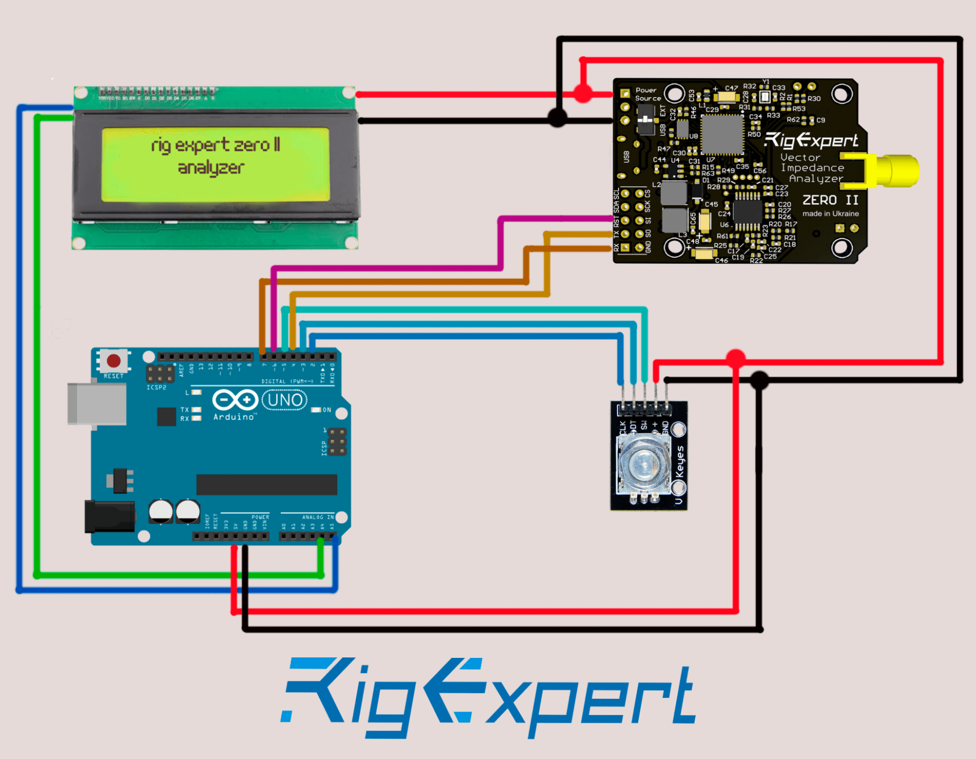
Connect all components according to this diagram
- RX pin of the analyzer to pin 7 of Arduino UNO
- TX pin of the analyzer to pin 4 of Arduino UNO
- Reset the pin of the analyzer to pin 6 of Arduino UNO
- SW pin of the encoder to pin 5 of Arduino UNO
- DT pin of the encoder to pin 3 of Arduino UNO
- CLK pin of the encoder to pin 2 of Arduino UNO
- SDA pin of the screen to A4 pin of Arduino UNO
- SCL pin of the screen to A5 pin of Arduino UNO
- Connect all +5 volt wires and connect them to the corresponding pin of Arduino UNO
- Connect all ground wires and connect them to the corresponding pin of Arduino UNO
After connecting all the components, connect Arduino to PC and upload the sketch. Before that, don’t forget to add the necessary libraries to the IDE. Otherwise, the program will not compile. Note that the encoder processing subroutine is already built into the body of the sketch (lines 34 to 140). Please do not change the code in these lines. If you are not going to use the encoder in your project, then this code can be removed.
After successfully loading the software code into Arduino, the text should be displayed on the LCD screen.
This project has four informational screens.
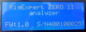
The first screen displays a welcome message, firmware version, and analyzer serial number.
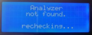
The second screen appears only if Arduino fails to connect with ZERO II.
Every 1 second, Arduino will try again and again. Make sure you have connected all wires properly. Make sure that the analyzer is powered on. Ensure that the dip switch of the power source selector is in the upper position.
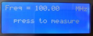
The third screen appears after a successful initialization of the analyzer.
This screen displays the set measurement frequency, as well as an invitation to press the encoder knob to start the measurement.
On the first startup, the working frequency will be set to 0. In the future, the current frequency will be remembered. The frequency can be changed by rotating the encoder knob. A normal rotation changes the frequency value by +/- 10 kHz. A rotation with the simultaneous pressing of the knob changes the frequency value by +/- 1 MHz (necessary for a quick change of the working frequency). Of course, entering the frequency is much more convenient using the keyboard. But implementing this process is already “homework” for you 🙂
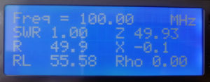
The fourth screen displays the measurement result.
In our case, we see the value of the working frequency, SWR, Z, R, X, Return Loss, and Rho (magnitude of the reflection coefficient). But this is not a complete list of parameters that can be obtained and displayed on the screen.
Below is a list of commands and parameters that ZERO II can return:
ZERO.getFwVersion();
ZERO.getMajorVersion();
ZERO.getMinorVersion();
ZERO.getHwRevision();
ZERO.getSerialNumber();
ZERO.getR();
ZERO.getRp();
ZERO.getX();
ZERO.getXp();
ZERO.getSWR();
ZERO.getRL();
ZERO.getZ();
ZERO.getPhase();
ZERO.getRho();
ZERO.getZ0().
In addition, the command ZERO.setZ0(double Z0) can be used to set the impedance value of the system.
Links to the components used:
- Arduino UNO: Amazon
- LCD I2C display: Amazon or Aliexpress
- Rotary encoder: Amazon or Aliexpress.
Problems you may encounter when implementing this project:
An unsuccessful attempt to compile the sketch.
Check if you have added all the necessary libraries. Check the correctness of selecting the Arduino model type and serial port number in the IDE settings.
After uploading the sketch, nothing is displayed on the LCD screen.
A trimmer resistor on the back of the screen adjusts the screen contrast. It may be necessary to adjust the contrast. Depending on the type of LCD controller used, the I2C address may differ. Check with the screen manufacturer for the address value. As a rule, the basic value is 0x27. This line specifies the address: LiquidCrystal_I2C lcd(0x27, 20, 4).
Depending on the type of LCD controller used, the I2C address of the screen may differ. Check with the screen manufacturer for the address value. Usually, the base value is 0x27. The address is written in this line: LiquidCrystal_I2C lcd(0x27, 20, 4).
The encoder knob does not change or incorrectly changes the working frequency value.
It may be due to the type of encoder used and the two variants of reading the rotation direction. Try changing the last two parameters here (0 or 1): encMinim enc(CLK, DT, SW, 1, 0).
The name of the library clearly indicates that data exchange between the analyzer and Arduino is carried out using the UART protocol.
However, ZERO II has other user interfaces. In the future, we also plan to create a library for the I2C protocol. Unlike AA-30.ZERO (which has a text format for commands), all commands and data in the ZERO II analyzer have a binary format.
You can familiarize yourself with the data format of the analyzer and learn other technical details in this manual.
Please feel free to ask us any questions. We are always available at email: [email protected] and on our Facebook page.

