RigExpert <br> AA-600

RigExpert AA-600

RigExpert AA-600, AA-1000 and AA-1400 are powerful antenna analyzers designed for testing, checking, tuning or repairing antennas and antenna feedlines. Graphical SWR (Standing Wave Ratio) and impedance, as well as Smith/polar chart displays are key features of these analyzers which significantly reduce the time required to adjust an antenna. Easy-to use measurement modes, as well as additional features such as connection to a personal computer make RigExpert AA-600, AA-1000 and AA-1400 attractive for professionals and hobbyists. The following tasks are easily accomplished by using these analyzers:

  • Rapid check-out of an antenna
  • Tuning an antenna to resonance
  • Antenna SWR and impedance measurement and comparison before and after specific event (rain, hurricane, etc.)
  • Making coaxial lines or measuring their parameters
  • Cable testing and fault location
  • Measuring capacitance or inductance of reactive loads

RigExpert
AA-600
Specifications

RigExpert <br> AA-600
Frequency range
  • 0.1 to 600 MHz
Frequency entry
  • 1 kHz resolution
SWR measurement range
  • 1 to 10 in graph mode
  • 1 to 100 in numerical modes
R and X range
  • 0…1000, -1000…1000 in graph mode
  • 0…10000, -10000…10000 in numerical modes
Display modes
  • R, X graph, 80 points
  • Smith (or polar) chart, 80 points
  • SWR at single or multiple frequencies
  • SWR graph, 80 points
  • SWR, return loss, R, X, Z, L, C at single frequency
  • TDR (Time Domain Reflectometer) graph
RF output
  • Connector type: N
  • Output power: -10 dBm (at a load of 50 ohms)
  • Output signal shape: square, 0.1 to 200 MHz. For higher frequencies, harmonics of the main signal are used.
Power
  • Max. 3 hours of continuous measurement, max. 2 days in stand-by mode when fully charged batteries are used
  • Three 1.2V, 1800…3000 mAh, Ni-MH batteries, type AA
  • When the analyzer is connected to a PC or a DC adapter with USB socket, it takes power from these sources
Interface
  • 320×240 color TFT display
  • 6x3 keys on the water-proof keypad
  • Multilingual menus and help screens
  • USB connection to a personal computer
Dimensions
  • 230x100x55 mm (9x4x2”)
Operating temperature
  • 0…40 °C (32…104 °F)
Weight
  • 650g (23 Oz)
Accessories inside the box
  • Battery charger
  • N-to-UHF adapter
  • NiMH rechargeable batteries (3 pcs)
  • RigExpert AA-600
  • Soft case with straps
  • USB cable
  • User’s manual
GTIN-13
  • 4820185420037
Note
  • Specifications are subject to change without notice
  • Мade in Ukraine
More

RigExpert AA-600 – How it works?

Structure diagram

The structure diagram of the RigExpert AA-600, AA-1000 and AA-1400 Antenna Analyzers is located below:

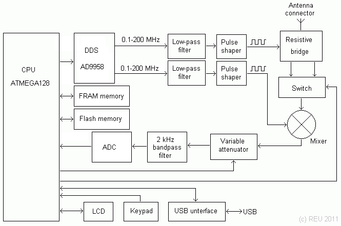
The “brain” of the analyzer is Atmel 8-bit RISC microcontroller. It controls a AD9958 DDS chip running at 500 MHz and generating two sinusoidal signals. Both signals are low-pass filtered and then put through pulse shapers, producing two square signals with LVDS levels. Resistive brigde was chosen to measure parameters of a load because of its simplicity and good frequency response. The switch commutates two outputs of the bridge. After the switch, the signal is mixed with the second channel output to produce audio frequency of 2 kHz. A variable attenuator is used to maintain the audio signal level in the desired range. This signal is then filtered and fed through the 16-bit ADC to the microcontroller. There is a simple relationship between the measurement frequency, DDS frequencies and attenuator division ratio:

Subband Measurement
frequency
DDS1
frequency
DDS2
frequency
Harmonic
number
Attenuator
ratio
1
(AA-600, AA-1000 and AA-1400)
0.1 … 200 MHz 0.1 … 200 MHz DDS1 + 2 kHz 1 /25
2
(AA-600, AA-1000 and AA-1400)
200 … 600 MHz 67 … 200 MHz DDS1 + 667 Hz 3 /3
3
(AA-1000 and AA-1400)
600 … 1000 MHz 120 … 200 MHz DDS1 + 400 Hz 5 /1
4
(AA-1400 only)
1000 … 1400 MHz 142 … 200 MHz DDS1 + 286 Hz 7 *2

The 320×240 color TFT display and the 6×3 keys keypad are connected directly to the CPU. The analyzer is equipped with 128K of external Flash memory to store measurement results, as well as with 32K of the fast external FRAM. The USB interface chip allows connecting the analyzer to the PC.

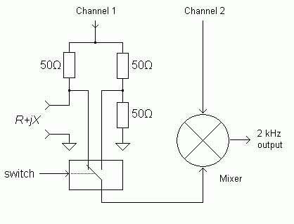
Close look at the bridge

This is a diagram of the resistive bridge and its connection to the mixer:

The switch which is controlled by the CPU feeds the signal from the certain side of the bridge to the mixer chip. When the load is totally active and its resistance is 50 Ω, the bridge is balanced and the switch outputs the same signal in both positions. This eliminates the need of calibration of the analyzer, also giving very good precision near SWR=1.

See also: Data exchange with RigExpert antenna analyzers