Designing the quarter-wave coaxial braid stub to achieve symmetry in the 50 MHz Yagi antenna
It is well known that the dipole is a symmetrical antenna. Connecting the unsymmetrical coaxial feedline directly to it will result in a distorted pattern and vertically polarized noise pickup.
Therefore, some measures must be taken to make the entire system (antenna plus feedline) symmetrical to optimize antenna performance.
There are various solutions employed by amateurs to achieve symmetry in HF and 50 MHz setups. These include creating a coaxial choke by winding up to 10 turns of the coaxial cable near the Yagi feed point or using multiple Amidon ferrite core rings on the coax. Both of these solutions are effective but can lead to a significant imbalance in weight on the boom.
In light of this, it was decided to explore the well-known VHF quarter-wave coaxial braid stub as an alternative approach.
-
Making the stub.
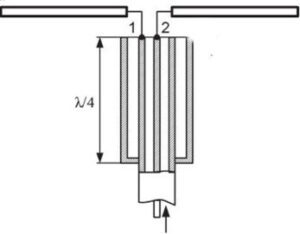
Cut the piece of coax at least 10cm longer than calculated by the formula:
L=300/50.2/4*K
where K is a reflection coefficient that equals:
- 0.66 for polyethylene,
- 0.707 for teflon
- 0.85 +/- for foam
-
Prepare the antenna end of the coaxial cable as follows:
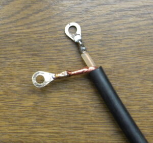
- remove at least 4 cm of the UV-resistant black PVC outer coax jacket
- unweave 3+ cm of the coax braid and twist it for soldering into the brass terminal later
- remove the inner coax dielectric and prepare the inner conductor for soldering into the brass terminal
- ensure that both leads, including the terminals, are not longer than 3 cm. REMEMBER: the length of the leads is included in the calculated driven element length
- crimp and solder the terminals.
-
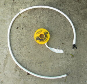
Preparing the extra braid as follows:
- Cut the 1.5m piece of an old 50 or 75 Ohm coax with an outer diameter equal or larger then the main
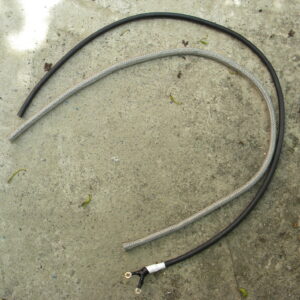 feedline (preferably)
 - remove the UV-resistant black PVC outer coax jacket
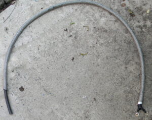
- carefully pull off the braid from the inner coax dielectric, trying not to deform it. The tube thus created will become the quarter-wave stub after it is pulled over the UV-resistant black PVC outer coax jacket.
Assuming the reflection coefficient of the polyethylene outer coax jacket is 0.66, the the length of the stub can be calculated using the formula mentioned above: Lst = 300 / 50.2 / 0.66 * 4 * 0.66 = 0.986 m.
-
Final adjustments and hints:
- wrap a thick Teflon tape around the main coax near the antenna terminals since the quarter-wave coaxial braid stub is at the high voltage potential at that point. Good RF insulation is needed to avoid RF arcs. Secure it with the 0.2mm X 20mm Teflon plumbing tape and wrap up the antenna end of the
 braid inwards to avoid accidental contact between the tiny braid wires and the center conductor or the main coax braid
 - pull the stub braid over the UV-resistant black PVC outer coax jacket. Tightly wrap the 0.2mm X 20mm Teflon plumbing tape over the stub braid. Then tightly wrap the black electric PVC tape over the Teflon plumbing tape. If these wrappings are done correctly, the stub braid will be fixed and won’t move
- pull 1 meter of the black UV-resistant black heat-shrinkable tubing of a suitable diameter over the stub and heat it with a fan. The stub is now ready for tuning and assembling
- carefully cut the coax to have a length of 1.02-1.05 meters, leaving the extra length for RF connector connection
- remove the UV-resistant black PVC outer coax jacket and join the main and stub braids together at 0.986m point for soldering to the connector’s body
- cut the inner dielectric and inner conductor for soldering to the central pin of the RF connector.
-
RF Connectors and Their Use with the Quarter-Wave Coaxial Braid Stub:
According to https://www.qsl.net/dk7zb/dk7zb-match.htm in order to suppress common-mode current, a simple solution is to ground the outer shield at a distance of λ/4 at the peak of the current. Therefore, in addition to the quarter-wave coaxial braid stub, connecting the body of the RF connector soldered at a distance of λ/4 should eliminate common-mode current completely.
There are several methods to attach the RF connector to the boom, and two of them are shown. Both methods require an easy-to-build mounting Aluminum plate.
Method 1. Solder the stub directly to the SO-239 or other female connector which is mounted on the mounting plate using stainless screws or rivets. It is important to ensure a careful sealing of both the SO-239 and PL-259 connectors to prevent water leakage.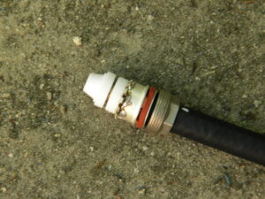
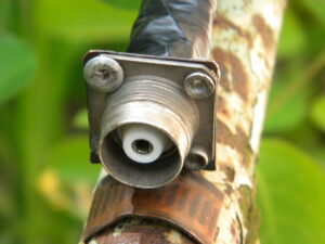
Method 2. This method is considered the best due to its electrical and mechanical advantages. Solder the stub into the sealed CP-50-163 female connector. These high-quality silver-plated RF connectors were manufactured across the former Soviet Union and are still available.
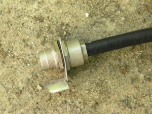
The connector is mounted to the mounting plate using a special nut and spring washer
Method 3. This method is similar to method 2 but utilizes a large sealed female N-connector instead. The design of the mounting plate depends on the specifications provided by the connector manufacturer.
The assembled mounting plate with a female stub connector is attached to the boom using the stainless hose clamp of the appropriate size.
- Checking the stub resonance.
Any suitable RigExpert antenna analyzer can be used to check the resonance of the stub.
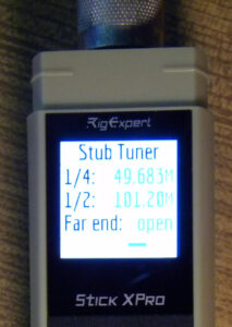
The RigExpert Stick Xpro analyzer which is small and handy was chosen to make the test.
The menu item 9 “StubT: Making ¼ and ½ wave stubs” gave the following results:
- ¼ – 49.683 MHz
- ½ -101.20 MHz
As the special N-to-CP50 adapter adds its length to the total stub length, the actual stub resonance is considered to be within the amateur band of 50-52 MHz.

