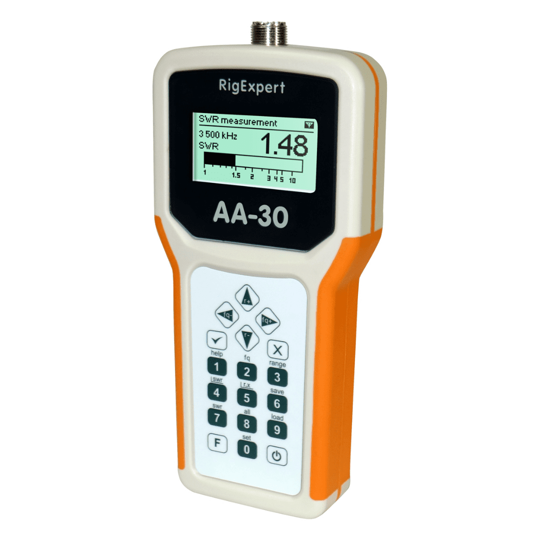
RigExpert AA-30

RigExpert AA-30

RigExpert AA-30 and AA-54 are powerful antenna analyzers designed for testing, checking, tuning or repairing antennas and antenna feedlines. Mainly, these are SWR (Standing Wave Ratio) and impedance measurement instruments (vector impedance analyzers). Easy-to use measurement modes, as well as additional features such as connection to a personal computer (to plot Smith charts, etc.), make RigExpert AA-30 and AA-54 attractive for professionals and hobbyists. It is quite important that graphical display of various parameters over a wide frequency range is a key feature of these analyzers which significantly reduces the time required to adjust an antenna. The following tasks are easily accomplished by using RigExpert AA-30 and AA-54:

  • Rapid check-out of an antenna
  • Tuning an antenna to resonance
  • Antenna SWR and impedance measurement and comparison before and after specific event (rain, hurricane, etc.)
  • Making coaxial lines or measuring their parameters
  • Cable testing and fault location
  • Measuring capacitance or inductance of reactive loads

RigExpert AA-30
Specifications

RigExpert AA-30
Frequency range
  • AA-30: 0.1 to 30 MHz
  • AA-54: 0.1 to 54 MHz
Frequency entry
  • 1 kHz
SWR measurement range
  • 1 to 10 in chart modes
R and X range
  • 0…10000, -10000…10000 in numerical modes
  • 0…200, -200…200 in graph mode
Display modes
  • R, X graph, 100 points
  • SWR at single or multiple frequencies
  • SWR graph, 100 points
  • SWR, return loss, R, X, Z, L, C at single frequency
RF output
  • Connector type: UHF (SO-239)
  • Output power: +13 dBm (at 50 Ohm load)
  • Output signal shape: square, 0.1…10 MHz (AA-30) or 0.1…10.8 MHz (AA-54). For higher frequencies, third or fifth (AA-54) harmonics are used
Power
  • Max. 3 hours of continuous measurement, max. 2 days in stand-by mode when fully charged batteries are used
  • Two 1.2V, 1800…2700 mA·h, Ni-MH batteries, type AA *
  • Two 1.5V alkaline batteries, type AA
  • When the analyzer is connected to a PC or a DC adapter with USB socket, it takes power from these sources
Interface
  • 128×64 graphical backlit LCD
  • 6x3 keys on the water-proof keypad
  • AA-54: multilingual menus and help screens, AA-30:menus and help screens in English language
  • USB connection to a personal computer
Dimensions
  • 22·10·3.6 cm (9·4·1.5”)
Operating temperature
  • 0…40 °C (32…104 °F)
Weight
  • 400g (14 Oz)
Accessories inside the box
  • Alkaline batteries
  • CD with drivers and software
  • RigExpert AA-30
  • Soft case (optional, not included in standard package)
  • Software manual
  • USB cable (optional, not included in standard package)
  • User’s manual
GTIN-13
  • 4820185420020
Note
  • Specifications are subject to change without notice
  • Мade in Ukraine
More

RigExpert AA-30 – How it works?

Structure diagram

The structure diagram of the RigExpert AA-30/AA-54 Antenna Analyzer is located below:

The “brain” of the analyzer is Atmel 8-bit RISC microcontroller. It controls two AD9833 DDS chips running at 25 MHz and generating two sinusoidal signals. Both signals are low-pass filtered and then put through pulse shapers, producing two square signals with CMOS levels. Resistive bridge was chosen to measure parameters of a load because of its simplicity and good frequency response. The switch commutates two outputs of the bridge. After the switch, the signal is mixed with the second channel output to produce audio frequency of 1.7 kHz. A variable attenuator is used to maintain the audio signal level in the desired range. This signal is then filtered and fed into the 10-bit ADC of the microcontroller. There is a simple relationship between the measurement frequency, DDS frequencies and attenuator division ratio:

Subband Measurement
frequency
DDS1
frequency
DDS2
frequency
Harmonic
number
Attenuator
ratio
1 0.1 … 10 MHz 0.1 … 10 MHz DDS1 + 1.744 kHz 1 /25
2 10 … 30 MHz 3.333 … 10 MHz DDS1 + 581 Hz 3 /3
3 (AA-54 only) 30 … 54 MHz 6 … 10.8 MHz DDS1 + 349 Hz 5 /1

The 128×64 graphical LCD and the 6×3 keys keypad are connected directly to the CPU. Also, the AA-54 is equipped with 128K of external Flash memory to store measurement results. The USB interface chip allows connecting the analyzer to the PC.

Close look at the bridge

This is a diagram of the resistive bridge and its connection to the mixer:

The switch which is controlled by the CPU feeds the signal from the certain side of the bridge to the mixer chip. When the load is totally active and its resistance is 50 Ω, the bridge is balanced and the switch outputs the same signal in both positions. This eliminates the need of calibration of the analyzer, also giving very good precision near SWR=1.

See also: Data exchange with RigExpert antenna analyzers