RigExpert IT-24 Antenna Analyzer Professional and Amateur Radio Use
RigExpert IT-24 is a universal portable device for testing and tuning antennas and antenna feedlines of the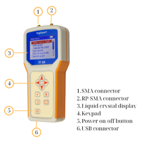 2.3 – 2.6 GHz band.
This device can be used by telecommunication providers, service companies, antenna/transmitter manufacturers, and radio amateurs for:
- Quick tests of antennas and RF coaxial cables
- Tuning, and repairing antennas and antenna feedlines in the 2.4 GHz band
- Output power measurement of 2.4 GHz transmitters and wireless access points
- RF environment monitoring in spectrum analyzer mode.
RigExpert IT-24 supports various technologies such as Wi-Fi, WiMAX, ZigBee, and proprietary data transfer protocols. Equipped with SMA and RP-SMA connectors, a liquid crystal display, and a USB connector, the IT -24 offers convenience and functionality for most wireless networks and radio communications testing needs.
Effective usage of RigExpert IT-24 starts with turning it ON by pressing the on/off (5) button.
The “Main Menu” shows up on the color LCD display showing the following options:
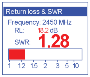
- Return loss & SWR
- SWR graph
- Calibrate RL/SWR (It is advisable to calibrate the analyzer before starting the measurements)
- Peak power
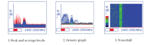
- Peak and average levels
- Density graph
- Waterfall
- Settings
- PC mode
- Help
To make the SWR, Return Loss (RL), and coaxial cable measurements connect your antenna coaxial feedline to the IT24 RP-SMA socket connector (2). If the main feedline is the hardline, use the proper SMA adaptor and the pigtail to connect to the RP-SMA socket connector. 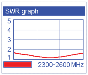
Choose the “Return loss & SWR” or “SWR graph” menu options and start measurements. The results of the antenna measurements will be shown on the color LCD display by pressing the V button. Stop measurements by pressing the X button.
Similar methods are used to check the quality of RF coaxial cables. Terminate the far end of the main feedline by UHF 50 Ohm dummy load that has low SWR (less than 1.2 at 2.4 GHz.) Choose the “Return loss & SWR” or “SWR graph” menu options and start measurements. If the measured SWR is less than 1.3 across the band, the coax can be used, if the SWR is 1.6 or higher, this cable is NOT suited for UHF and microwave applications due to excessive internal RF losses.
The next you can use the IT-24 “Spectrum analyzer” capabilities to monitor the local RF environment and measure electromagnetic compatibility.
The “Peak and average levels”, “Density graph” and “Waterfall” menu options allow showing the local RF environment at the IT-24 color LCD display for user convenience in three different methods.
Finally, the output power of any 2.4 GHz power source less than 1 watt can be measured by connecting it via the SMA pigtail and proper adapters to the SMA socket connector (1).
Choose the “Peak power” menu option and press the V button.
Measurement results are shown on the IT-24 color LCD display.
Stop measurements by pressing the X button.
There is a “PC mode ”menu option to connect the RigExpert IT-24 to a personal computer via USB port. This allows to update the firmware as well. To get the latest software and firmware for IT-24 please visit the IT-24 product page https://rigexpert.com/products/uhf-analyzers/it-24/ or get in touch with RigExpert technical support at [email protected]
RigExpert IT-24 can be successfully used to evaluate the
transmitting part of the QO-100 Es’hail-2 Geostationary Satellite ground station.
The two most popular antenna types for 2.4 GHz used to illuminate the reflecting parabola surface are helix and patch antennas.
Both are easy to build, and the major task is to tune them to the desired frequency.
With the RigExpert IT-24, this will take several minutes to find the
antenna’s resonant frequency, input impedance, and decide what
actions need to be done if necessary:
- Connect 2.4 GHz antenna coax to the RigExpert IT-24 RP SMA socket 2;
- Choose the “SWR graph” menu item, and press the V button;
- Select the second sub-band (2.4-2.5 GHz) uplink frequency by pressing Left and Right keys. Amateurs are transmitting 250 kHz bandwidth on 2400.050 – 2400.300 MHz. Watch the field bar and the numbers at the bottom of the screen.
- Choose the “Return loss & SWR” menu item press V button and both parameters at the center of the chosen sub-band frequency will be shown on the screen.
Stop measurements by pressing the X button.
After tuning, the antenna is mounted at the reflector’s focal point.
The RigExpert IT-24 analyzer sweep signal can be monitored by a new RigExpert Fobos SDR https://rigexpert.com/products/kits/fobos-sdr/
IT-24 signal is radiated by a resonant whip antenna and is received at RF (25 to 6000 MHz) SDR input via RF field.
The 2.3-2.4 GHz sweep is clearly seen on the HDSDR https://www.hdsdr.de/ software screen.


